
Product Info

Smart LTE Module Series
SC66 Hardware Design
SC66_Hardware_Design 97 / 118
1)
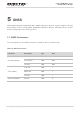
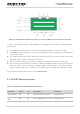
The bandwidth of LTE-TDD B41 for SC66-CE and SC66-J is 120MHz (2535MHz~2655MHz), and the
corresponding channel ranges from 40040 to 41240.
2)
The bandwidth of LTE-TDD B41 for SC66-A and SC66-E is 200MHz(2496MHZ~2690MHz), and the
corresponding channel ranges from 39650~41589.
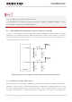
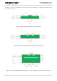
6.1.1. Main and Rx-diversity Antenna Interfaces Reference Design
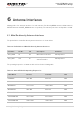
A reference circuit design for main and Rx-diversity antenna interfaces is shown as below. A π-type
matching circuit should be reserved for better RF performance, and the π-type matching components
(R1/C1/C2, R2/C3/C4) should be placed as close to the antennas as possible. The capacitors are not
mounted by default and resistors are 0Ω.
ANT_MAIN
R1 0R
C1
Module
Main
antenna
NM
C2
NM
R2 0R
C3
Diversity
antenna
NM
C4
NM
ANT_DRX
Figure 34: Reference Circuit Design for Main and Rx-diversity Antenna Interfaces
6.1.2. Reference Design of RF Layout
For user’s PCB, the characteristic impedance of all RF traces should be controlled as 50Ω. The
impedance of the RF traces is usually determined by the trace width (W), the materials’ dielectric constant,
the distance between signal layer and reference ground (H), and the clearance between RF trace and
ground (S). Microstrip line or coplanar waveguide line is typically used in RF layout for characteristic
NOTE