
Product Info

Smart LTE Module Series
SC66 Hardware Design
SC66_Hardware_Design 71 / 118
DSI1_CLK_P
LEDA
NC
LEDK
NC (SDA-TP)
VIO18
NC (VTP-TP)
DSI1_LN3_P
LCD1_RST
DSI1_LN3_N
DSI1_LN2_P
DSI1_CLK_N
DSI1_LN2_N
RESET
LCD_ID
NC (SCL-TP)
NC (RST-TP)
NC (EINT-TP)
GND
VCC28
GND
MIPI_TDP3
MIPI_TDN3
GND
MIPI_TDP2
MIPI_TDN2
GND
MIPI_TDP1
MIPI_TDN1
GND
LDO3B_2P8
LDO11A_1P8
LCM1 _ LED+
LCM1 _LED-
1
2
3
4
5
6
7
8
9
10
12
13
14
15
16
17
18
19
20
21
22
23
24
25
26
27
MIPI_TDP0
MIPI_TDN0
GND
MIPI_TCP
MIPI_TCN
29
28
30
3
4
5
6
3
4
5
6
3
4
5
6
3
4
5
6
DSI1_LN1_N
DSI1_LN1_P
DSI1_LN0_N
DSI1_LN0_P
1
2
3
4
5
6
11
1
2
1
2
1
2
1
2
100nF4.7uF
1uF
Module
LCM
FL1
FL2
FL3
FL4
FL5
EMI filter
C3C2C1
NC
GND
GND
GND
GND
ADC1
31
32
33
34
NC
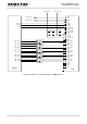
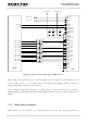
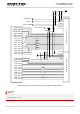
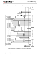
Figure 23: Reference Circuit Design for LCM1 Interface
MIPI are high speed signal lines. It is recommended that common-mode filters should be added in series
near the LCM connector, so as to improve protection against electromagnetic radiation interference.
ICMEF112P900MFR using ICT is recommended.
When compatible design with other displays is required, please connect the LCD_ID pin of LCM to the
module’s ADC pin, and please note that the output voltage of LCD_ID cannot exceed the voltage range of
ADC pin.
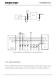
3.19. Touch Panel Interfaces
SC66 provides two I2C interfaces for connection with Touch Panel (TP), and also provides the