
Product Info


Smart LTE Module Series
SC66 Hardware Design
SC66_Hardware_Design 61 / 118
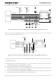
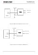
In order to offer good ESD protection, it is recommended to add a TVS diode array with parasitic
capacitance not exceeding 50pF. The 22Ω resistors should be added in series between the module
and (U)SIM card so as to suppress EMI spurious transmission and enhance ESD protection. Please
note that the (U)SIM peripheral circuit should be close to the (U)SIM card connector.
The 22pF capacitors should be added in parallel on USIM_DATA, USIM_VDD, USIM_CLK and
USIM_RST signal lines so as to filter RF interference, and they should be placed as close to the
(U)SIM card connector as possible.
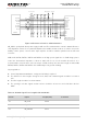
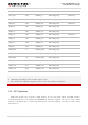
3.12. SD Card Interface
SC66 module supports SD 3.0 specifications. The pin definition of the SD card interface is shown below.
Table 18: Pin Definition of SD Card Interface
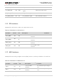
A reference circuit for SD card interface is shown as below.
Pin Name
Pin No.
I/O Description
Comment
SD_VDD
63
PO
Power supply for SD card
Vnorm=2.95V
I
O
max=600mA
SD_PU_VD
D
179
PO
SD card pull-up power
supply
Support 1.8V/2.95V power supply. The
maximum drive current is 50mA.
SD_CLK
70
DO
High speed digital clock
signal of SD card
Control characteristic impedance as
50Ω.
SD_CMD
69
I/O
Command signal of SD card
SD_DATA0
68
I/O
High speed bidirectional
digital signal lines of SD
card
SD_DATA1
67
I/O
SD_DATA2
66
I/O
SD_DATA3
65
I/O
SD_DET
64
DI
SD card insertion detection
Active low.