
Product Info


Smart LTE Module Series
SC66 Hardware Design
SC66_Hardware_Design 60 / 118
USIM_ VDD
USIM_ RST
USIM_ CLK
USIM_ DATA
USIM_ DET
22R
100K
100nF
(U)SIM Card Connector
ESD
22pF
VCC
RST
CLK
IO
VPP
GND
USIM_ VDD
10K
Module
R1
R2
C1
22pF22pF
C2 C3 C4
D1
22R
22R
R3
R4
R5
LDO13A_1P8
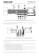
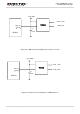
Figure 17: Reference Circuit for (U)SIM Interface with an 8-pin (U)SIM Card Connector
If there is no need to use USIM_DET, please keep it open. The following is a reference circuit for (U)SIM
interface with a 6-pin (U)SIM card connector.
Module
USIM_ VDD
USIM_ RST
USIM_ CLK
USIM_ DATA
22R
22R
22R
100nF
ESD
22pF
VCC
RST
CLK IO
VPP
GND
10K
USIM_VDD
22pF
22pF
R1
C1
D1
R2
R3
R4
C2 C3 C4
USIM_ DET
(U)SIM Card Connector
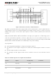
Figure 18: Reference Circuit for (U)SIM Interface with a 6-pin (U)SIM Card Connector
In order to ensure good performance and avoid damage of (U)SIM cards, please follow the criteria below
in (U)SIM circuit design:
Keep placement of (U)SIM card connector as close to the module as possible. Keep the trace length
of (U)SIM card signals as less than 200mm as possible.
Keep (U)SIM card signals away from RF and VBAT traces.
A filter capacitor shall be reserved for USIM_VDD, and its maximum capacitance should not exceed
1uF. The capacitor should be placed near to (U)SIM card.
To avoid cross-talk between USIM_DATA and USIM_CLK, keep them away from each other and
shield them with ground. USIM_RST also needs ground protection.