
Product Info

Smart LTE Module Series
SC66 Hardware Design
SC66_Hardware_Design 102 / 118
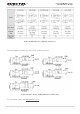
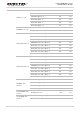
6.3.2. Recommended Circuit for Active Antenna
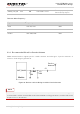
The active antenna is powered by a 56nH inductor through the antenna's signal path. The common power
supply voltage ranges from 3.3V to 5.0V. Although featuring low power consumption, the active antenna
still requires stable and clean power supplies. It is recommended to use high performance LDO as the
power supply. A reference design of GNSS active antenna is shown below.
Active Antenna
3V3
Module
ANT_GNSS
56nH
10R
1uF
100pF
NM
NM
C4
C1
R1
L1
R2
0R
C5
C3
C2
100pF
Figure 41: Reference Circuit Design for GNSS Active Antenna
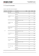
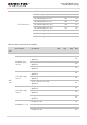
6.4. Antenna Installation
6.4.1. Antenna Requirements
The following table shows the requirements on main antenna, Rx-diversity, Wi-Fi/BT antenna and GNSS
antenna.
Table 45: Antenna Requirements
Antenna Type
Requirements
GSM/WCDMA/TD-SCDMA/
LTE
VSWR: ≤ 2
Gain (dBi): 1
Max Input Power (W): 50
Input Impedance (Ω): 50
Polarization Type: Vertical
Cable Insertion Loss: < 1dB
(frequency:663-960 MHz )
Cable Insertion Loss: < 1.5dB( frequency:1427-2200 MHz )
Cable Insertion Loss: < 2dB ( frequency:2300-2690 MHz )
Wi-Fi/BT
VSWR: ≤ 2
Gain (dBi): 1
Max Input Power (W): 50