
Product Info


LTE Module Series
EG25-G Mini PCIe Hardware Design
EG25-G_Mini_PCIe_Hardware_Design 27 / 48
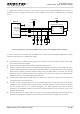
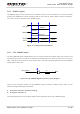
3.8.4. PERST# Signal
The PERST# signal can be used to force a hardware reset on the card. Customers can reset the module
by driving the PERST# to a low level voltage with the time frame of 150ms~460ms and then releasing it.
The reset scenario is illustrated in the following figure.
V
IL
≤0.5V
V
IH
≥2.3V
VCC_3V3
≥150ms
Resetting
Module
Status
Running
PERST#
Restart
≤460ms
Figure 11: Timing of Resetting Module
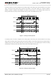
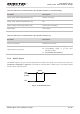
3.8.5. LED_WWAN# Signal
The LED_WWAN# signal of EG25-G Mini PCIe is used to indicate the network status of the module, and
can absorb the current up to 40mA. According to the following circuit, in order to reduce the current of the
LED, a resistor must be placed in series with the LED. The LED is emitting light when the LED_WWAN#
output signal is active low.
LED_WWAN#
VCC
R
Figure 12: LED_WWAN# Signal Reference Circuit Diagram
There are two indication modes for LED_WWAN# signal to indicate network status, which can be
switched through following AT commands:
AT+QCFG=“ledmode”,0 (Default setting)
AT+QCFG=“ledmode”,2
The following tables show the detailed network status indications of the LED_WWAN# signal.