
Product Info

LTE Module Series
EG25-G Hardware Design
EG25-G_Hardware_Design 53 / 100
Module
WAKE_ON_WIRELESS
WLAN_SLP_CLK
PM_ENABLE
DCDC/LDO
32KHZ_IN
WAKE_ON_WIRELESS
FC20 Module
VDD_3V3
POWER
SDC1_DATA3
SDC1_DATA2
SDC1_DATA1
SDC1_DATA0
SDC1_CLK
SDC1_CMD
WLAN_EN
SDIO_D3
SDIO_D2
SDIO_D1
SDIO_D0
SDIO_CLK
SDIO_CMD
WLAN_EN
WLAN
BT_EN
BT_RTS
BT_CTS
BT_TXD
BT_RXD
PCM_IN
PCM_OUT
PCM_SYNC
PCM_CLK
BT_EN
BT_UART_RTS
BT_UART_CTS
BT_UART_RXD
BT_UART_TXD
PCM_OUT
PCM_IN
PCM_SYNC
PCM_CLK
VDD_EXT VIO
COEX_UART_TX
COEX_UART_RX LTE_UART_TXD
LTE_UART_RXD
COEX
Bluetooth*
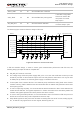
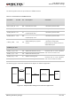
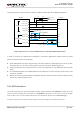
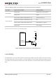
Figure 26: Reference Circuit of Wireless Connectivity Interfaces with FC20 Module
1. FC20 module can only be used as a slave device.
2. When BT function is enabled on EG25-G module, PCM_SYNC and PCM_CLK pins are only used to
output signals.
3.
1)
Pads 24~27 are multiplexing pins used for audio design on EG25-G module and BT function on
FC20 module.
4. “*” means under development.
5. For more information about wireless connectivity interfaces, please refer to document [5].
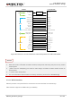
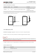
3.14.1. WLAN Interface
EG25-G provides a low power SDIO 3.0 interface and control interface for WLAN design.
SDIO interface supports the SDR mode (up to 50MHz).
NOTES