
Product Info

LTE Module Series
EG25-G Hardware Design
EG25-G_Hardware_Design 40 / 100
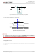
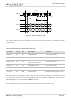
RESET_N
S2
Close to S2
TVS
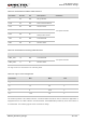
Figure 15: Reference Circuit of RESET_N by Using Button
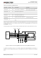
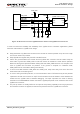
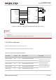
The reset scenario is illustrated in the following figure.
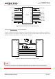
V
IL
≤0.5V
V
IH
≥1.3V
VBAT
≥150ms
Resetting
Module
Status
Running
RESET_N
Restart
≤460ms
Figure 16: Timing of Resetting Module
1. Use RESET_N only when failed to turn off the module by AT+QPOWD command and PWRKEY pin.
2. Ensure that there is no large capacitance on PWRKEY and RESET_N pins.
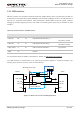
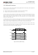
3.9. (U)SIM Interface
The (U)SIM interface circuitry meets ETSI and IMT-2000 requirements. Both 1.8V and 3.0V (U)SIM cards
are supported.
NOTES