
Product Info

LTE Module Series
BG96 Hardware Design
BG96_Hardware_Design 45 / 81
3.9. USB Interface
BG96 contains one integrated Universal Serial Bus (USB) interfacewhich complies with the USB 2.0
specification and supports high-speed (480Mbps) and full-speed (12Mbps)modes. The USB interface is
used for AT command communication, data transmission, software debugging and firmware upgrade. The
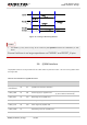
following table shows the pin definition of USB interface.
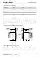
Table 10: Pin Definitionof USB Interface
For more details about USB 2.0 specification, please visithttp://www.usb.org/home
.
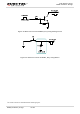
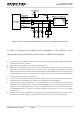
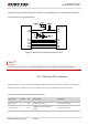
The USB interface is recommended to be reserved for firmware upgrade in customers’designs. The
following figure shows areference circuit of USB interface.
Figure 15: Reference Circuit of USB Interface
A common mode choke L1 is recommended to be added in series between the module and customer’s
MCU in order to suppress EMI spurious transmission. Meanwhile, the 0Ω resistors (R3 and R4) should be
Pin Name Pin No. I/O Description Comment
USB_VBUS 8 PI USB connection detection Typically 5.0V
USB_DP 9 IO USB differential data bus (+)
Require differential
impedance of 90Ω
USB_DM 10 IO USB differential data bus (-)
Require differential
impedance of 90Ω
GND 3 Ground