
User's Manual


LTE Module Series
EC21 Hardware Design
EC21_Hardware_Design Confidential / Released 86 / 94
8.2. Manufacturing and Soldering
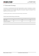
Push the squeegee to apply the solder paste on the surface of stencil, thus making the paste fill the
stencil openings and then penetrate to the PCB. The force on the squeegee should be adjusted
properlyso as to produce a clean stencil surface on a single pass. To ensure the module soldering quality,
thethickness of stencil for the module is recommended to be 0.18mm. For more details, please refer
todocument [4].
It is suggested that the peak reflow temperature is from 235 to 245ºC (for SnAg3.0Cu0.5 alloy). The
absolute maximum reflow temperature is 260ºC. To avoid damage to the module caused by repeated
heating, it is suggested that the module should be mounted after reflow soldering for the other side of
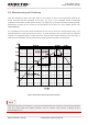
PCB has been completed. Recommended reflow soldering thermal profile is shown below:
Figure 45: Reflow Soldering Thermal Profile
During manufacturing and soldering, or any other processes that may contact the module directly, NEVER
wipe the module label with organic solvents, such as acetone, ethyl alcohol, isopropyl alcohol,
trichloroethylene, etc.
NOTE