
User's Manual


LTE Module Series
EC21 Hardware Design
EC21_Hardware_Design Confidential / Released 54 / 94
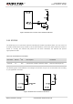
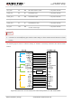
3.18. Wireless Connectivity Interfaces
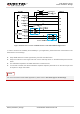
EC21supports a low-power SDIO 3.0 interface for WLAN and a UART/PCM interface for BT.
The following table shows the pin definition of wireless connectivity interfaces.
Table 22: Pin Definition of Wireless Connectivity Interfaces
Pin Name Pin No. I/O Description Comment
WLAN Part
SDC1_DATA3 129 IO SDIO data bus D3 1.8V power domain
SDC1_DATA2 130 IO SDIO data bus D2 1.8V power domain
SDC1_DATA1 131 IO SDIO data bus D1 1.8V power domain
SDC1_DATA0 132 IO SDIO data bus D0 1.8V power domain
SDC1_CLK 133 DO SDIO clock 1.8V power domain
SDC1_CMD 134 IO SDIO command 1.8V power domain
WLAN_EN 136 DO
WLAN function control via
FC20 module. Active high.
1.8V power domain
Coexistence and Control Part
PM_ENABLE 127 DO External power control 1.8V power domain
WAKE_ON_
WIRELESS
135 DI
Wake up the host (EC21 module)
by FC20 module.
1.8V power domain
COEX_UART_RX 137 DI LTE/WLAN&BT coexistence signal 1.8V power domain
COEX_UART_TX 138 DO LTE/WLAN&BT coexistence signal 1.8V power domain
WLAN_SLP_CLK 118 DO WLAN sleep clock
BT Part*
BT_RTS* 37 DI BT UART request to send 1.8V power domain
BT_TXD* 38 DO BT UART transmit data 1.8V power domain
BT_RXD* 39 DI BT UART receive data 1.8V power domain