
User's Manual

LTE Module Series
EC21 Hardware Design
EC21_Hardware_Design Confidential / Released 45 / 94
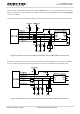
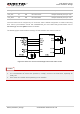
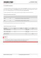
Figure 21: Reference Circuit with Transistor Circuit
Transistor circuit solution is not suitable for applications with high baud rates exceeding 460Kbps.
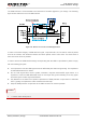
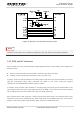
3.12. PCM and I2C Interfaces
EC21 provides one Pulse Code Modulation (PCM) digital interface for audio design, which supports the
following modes:
Primary mode (short frame synchronization, works as both master and slave)
Auxiliary mode (long framesynchronization, works as master only)
In primary mode, the data is sampled on the falling edge of the PCM_CLK and transmitted on the rising
edge.The PCM_SYNC falling edge represents the MSB. In this mode, PCM_CLK supports
128,256,512,1024 and2048kHz for different speech codecs.
In auxiliary mode, the data is also sampled on the falling edge of the PCM_CLK and transmitted on the
rising edge.But the PCM_SYNC rising edge represents the MSB. In this mode, PCM interface operates
with a 128kHz PCM_CLK and an 8kHz, 50% duty cycle PCM_SYNC only.
EC21 supports 8-bit A-law* andμ-law*, and also 16-bit linear data formats. The following figures show
theprimary mode’s timing relationship with 8kHz PCM_SYNC and 2048kHz PCM_CLK, as well asthe
auxiliary mode’s timing relationship with 8kHz PCM_SYNC and 128kHz PCM_CLK.
NOTE