
User's Manual


LTE Module Series
EC21 Hardware Design
EC21_Hardware_Design Confidential / Released 39 / 94
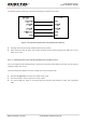
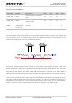
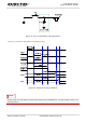
The reset scenario is illustrated inthe following figure.
Figure 16: Timing of Resetting Module
1. Use RESET_N only when turning off the module by AT+QPOWD command and PWRKEY pin failed.
2. Ensure that there is no large capacitance on PWRKEY and RESET_N pins.
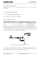
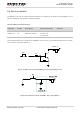
3.9. USIM Card Interface
The USIM card interface circuitrymeets ETSI and IMT-2000 SIM interface requirements. Both 1.8V and
3.0V USIM cards are supported.
Table 9: Pin Definition of the USIM Card Interface
Pin Name Pin No. I/O Description Comment
USIM_VDD 14 PO Power supply for USIM card
Either 1.8V or 3.0V is supported
by the module automatically.
USIM_DATA 15 IO Data signal of USIM card
USIM_CLK 16 DO Clock signal of USIM card
USIM_RST 17 DO Reset signal of USIM card
USIM_
PRESENCE
13 DI USIM card insertion detection
USIM_GND 10 Specified ground for USIM card
NOTES