
User's Manual


LTE Module Series
BG96 Hardware Design
BG96_Hardware_Design Confidential / Released 58 / 71
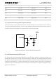
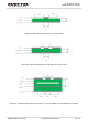
5.3.4. Coplanar Waveguide Structure Design
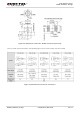
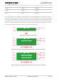
The recommended coplanar waveguide structure is shown as Figure 2.
Figure 34: Structure of Coplanar WG
The factors which influence impedance include dielectric constant (usually 4.2~4.6, here is 4.4), dielectric
height (H), RF trace width (W), the space between RF trace, the ground (S) and copper thickness (T).
When T=0.035mm, the recommended value of W and S for 50 ohm coplanar WG under different PCB
structure is listed in Table 1.
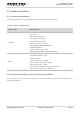
Table 28: Recommended Value of W and S for 50 ohm Coplanar WG under Different PCB Structure
Dielectric Height (H)
RF Trace Width (W)
Space between RF Trace and the
Ground (S)
0.076mm
0.1188mm
0.15mm
0.1mm
0.1623mm
0.2mm
0.15mm
0.24mm
0.2mm
0.8mm
0.8mm
0.18mm
1.0mm
0.8mm
0.17mm