
User's Manual

LTE Module Series
BG96 Hardware Design
BG96_Hardware_Design Confidential / Released 40 / 71
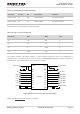
Table 13: Pin Definition of UART3 Interface
Pin Name
Pin No.
I/O
Description
Comment
UART3_TXD
27
DO
Transmit data
1.8V power domain
UART3_RXD
28
DI
Receive data
1.8V power domain
The logic levels are described in the following table.
Table 14: Logic Levels of Digital I/O
Parameter
Min.
Max.
Unit
V
IL
-0.3
0.6
V
V
IH
1.2
2.0
V
V
OL
0
0.45
V
V
OH
1.35
1.8
V
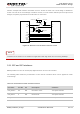
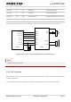
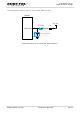
The module provides 1.8V UART interface. A level translator should be used if your application is
equipped with a 3.3V UART interface. A level translator TXS0108EPWR provided by Texas Instrument is
recommended. The following figure shows a reference design.
VCCA VCCB
OE
A1
A2
A3
A4
A5
A6
A7
A8
GND
B1
B2
B3
B4
B5
B6
B7
B8
VDD_EXT
RI
DCD
RTS
RXD
DTR
CTS
TXD
51K
51K
0.1uF
0.1uF
RI_MCU
DCD_MCU
RTS_MCU
RXD_MCU
DTR_MCU
CTS_MCU
TXD_MCU
VDD_MCU
Translator
Figure 18: Reference Circuit with Translator Chip
Please visit http://www.ti.com for more information.