
User's Manual

LTE Module Series
BG96 Hardware Design
BG96_Hardware_Design Confidential / Released 28 / 71
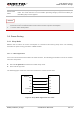
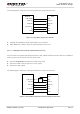
The following figure shows the connection between the module and the host.
USB_VBUS
USB_DP
USB_DM
AP_READY*
VDD
USB_DP
USB_DM
GPIO
Module Host
GND
GND
RI
EINT
Figure 5: Sleep Mode Application with RI
Sending data to BG96 through USB will wake up the module.
When BG96 has a URC to report, RI signal will wake up the host.
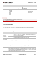
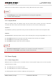
3.4.1.4. USB Application without USB Suspend Function
If the host does not support USB suspend function, USB_VBUS should be disconnected via an additional
control circuit to let the module enter into sleep mode.
Execute AT+QSCLK=1 command to enable sleep mode.
Ensure the DTR is held in high level or keep it open.
Disconnect USB_VBUS.
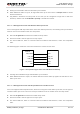
The following figure shows the connection between the module and the host.
USB_VBUS
USB_DP
USB_DM
AP_READY
VDD
USB_DP
USB_DM
GPIO
Module Host
RI
EINT
Power
Switch
GPIO
GND
GND
Figure 6: Sleep Mode Application without Suspend Function