
User's Manual

Wi-Fi&BT Module Series
FC20 Series Hardware Design
FC20_Series_Hardware_Design Confidential / Released 26 / 47
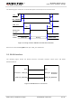
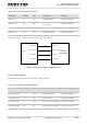
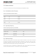
The following figure shows the reference design for UART interface connection between FC20 and EC20
R2.0/EC21/EC25.
CTS
RTS
RXD
TXD
FC20
RXD
TXD
RTS
CTS
EC20 R2.0/
EC21/EC25
Figure 9: Reference Design for UART Interface Connection
3.7. Coexistence Interface
Coexistence function is only supported by FC20. Please keep these pins open in FC20-N.
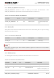
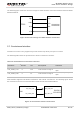
The following table shows the pin definition of FC20’s coexistence interface.
Table 12: Pin Definition of Coexistence Interface
Pin Name
Pin No.
I/O
Description
Comment
LTE_UART_TXD
5
DO
LTE coexistence signal
If unused, keep this pin
open.
LTE_UART_RXD
6
DI
LTE coexistence signal
If unused, keep this pin
open.
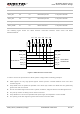
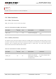
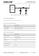
FC20 module supports LTE-WLAN coexistence and LTE-BT coexistence. The following figure shows
the coexistence interface connection between FC20 and EC20 R2.0/EC21/EC25.
LTE_UART_RXD
LTE_UART_TXD
FC20
COEX_UART_RX
COEX_UART_TX
EC2 R2.0/
EC21/EC25
Figure 10: Coexistence Interface Connection