
User's Manual


GSM/GPRS/GNSS Module Series
MC60 Hardware Design
MC60_Hardware_Design Confidential / Released 73 / 99
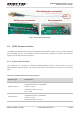
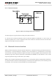
Figure 43: RF Soldering Sample
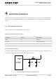
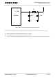
4.2. GNSS Antenna Interface
The GNSS part of MC60 module supports both GPS and GLONASS systems. The RF signal is obtained
from the GNSS_ANT pin. The impedance of RF trace should be controlled as 50 Ohm, and the trace
length should be kept as short as possible.
4.2.1. Antenna Specifications
The module can be connected to a dedicated GPS/GLONASS passive or active antenna to receive
GPS/GLONASS satellite signals. The recommended antenna specifications are given in the following
table.
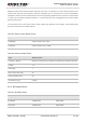
Table 30: Recommended Antenna Specifications
Antenna Type Specification
Passive Antenna
GPS frequency: 1575.42±2MHz
GLONASS frequency: 1602±4MHz
VSWR: <2 (Typ.)
Polarization: RHCP or Linear
Gain: >0dBi
Active Antenna
GPS frequency: 1575.42±2MHz
GLONASS frequency:1602±4MHz
VSWR: <2 (Typ.)
Polarization: RHCP or Linear