
User's Manual

GSM/GPRS/GNSS Module Series
MC60 Hardware Design
MC60_Hardware_Design Confidential / Released 28 / 99
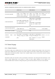
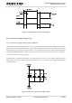
Figure 5: Voltage Ripple during Transmitting
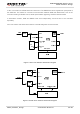
3.3.2. Decrease Supply Voltage Drop
3.3.2.1. Decrease Supply Voltage Drop for GSM Part
Power supply range of the GSM part is from 3.3V to 4.6V. Make sure that the input voltage will never drop
below 3.3V even in a burst transmission. If the power voltage drops below 3.3V, the module will be turned
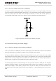
off automatically. For better power performance, it is recommended to place a 100uF tantalum capacitor
with low ESR (ESR=0.7Ω) and ceramic capacitors 100nF, 33pF and 10pF near the VBAT pin. A reference
circuit is illustrated in the following figure.
The VBAT trace should be wide enough to ensure that there is not too much voltage drop during burst
transmission. The width of trace should be no less than 2mm; and in principle, the longer the VBAT trace,
the wider it will be.
Figure 6: Reference Circuit for the VBAT Input