
User's Manual

GSM/GPRS/GNSS Module Series
MC60 Hardware Design
MC60_Hardware_Design Confidential / Released 27 / 99
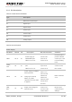
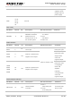
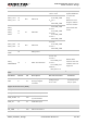
Table 8: Comparison between All-in-one and Stand-alone Solution
3.3. Power Supply
3.3.1. Power Features
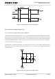
The power supply of the GSM part is one of the key issues in MC60 module design. Due to the 577us
radio burst in GSM part every 4.615ms, the power supply must be able to deliver high current peaks in a
burst period. During these peaks, drops on the supply voltage must not exceed the minimum working
voltage of the module.
For MC60 module, the maximum current consumption could reach 1.6A during a burst transmission. It will
cause a large voltage drop on the VBAT. In order to ensure stable operation of the module, it is
recommended that the maximum voltage drop during the burst transmission does not exceed 400mV.
All-in-one. Stand-alone Remarks
Firmware upgrade
Firmware upgrade via
UART Port (GSM and
GNSS Parts share the
same firmware package)
Firmware upgrade via
UART Port (GSM and
GNSS Parts share the
same firmware package)
Refer to 3.7.1.3
for details
Data transmission
Both GSM and GNSS data
are transmitted through
the GSM UART Port
GSM data is transmitted
through the GSM UART
Port.
GNSS data is transmitted
through the GNSS UART
Port.
GNSS TURN ON/OFF
By AT command through
GSM UART Port
Through the external
switch of MCU
Refer to 3.5 and
3.6 for details
GNSS wake up GSM
GNSS can wake up GSM
by interrupts
N/A
GNSS’s EPO data
download
EPO data is downloaded
directly through the GSM
part.
MCU receives the EPO
data which is downloaded
through the GSM part, and
then transmit it to the
GNSS part.
Refer to 3.14 for
details