
User's Manual

GSM/GPRS/GNSS Module Series
MC60 Hardware Design
MC60_Hardware_Design Confidential / Released 22 / 99
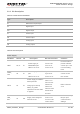
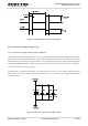
2.2~4.7uF bypass
capacitor, when
using this pin for
power supply.
GND
14,27,
31,40,
42,44,
45,48,
49
Ground
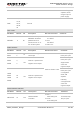
Turn on/off
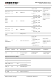
PIN Name PIN No. I/O Description DC Characteristics Comment
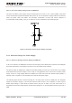
PWRKEY 5 DI
Power on/off key.
PWRKEY should be
pulled down for a
moment to turn on or
turn off the system.
V
IL
max=
0.1×VBAT
V
IH
min=
0.6×VBAT
V
IH
max=3.1V
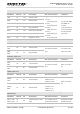
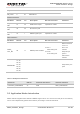
Audio Interface
PIN Name PIN No. I/O Description DC Characteristics Comment
MICP
MICN
1,
2
AI
Positive and negative
voice input
Refer to Section 3.8.6
If unused, keep
these pins open.
SPKP
SPKN
3,
4
AO
Channel 1 positive and
negative voice output
If unused, keep
these pins open.
Support both
voice and
ringtone output.
LOUD
SPKP
LOUD
SPKN
54
53
AO
Channel 2 positive and
negative voice output
1. If unused, keep
these pins open.
2. Integrate a
Class- AB
amplifier
internally.
3. Support both
voice and
ringtone output.
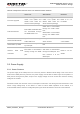
Network Status Indicator
PIN Name PIN No. I/O Description DC Characteristics Comment
NETLIGHT 47 DO
Network status
indication
V
OH
min=
0.85×VDD_EXT
V
OL
max=
0.15×VDD_EXT
If unused, keep
this pin open.