
User's Manual

GSM/GPRS/GNSS Module Series
MC20 Hardware Design
MC20_Hardware_Design Confidential / Released 76 / 95
1.
1)
Power control level PCL 5.
2.
2)
Power control level PCL 0.
3.
3)
Under the GSM850 and EGSM900 spectrum, the power of 1Rx and 4Tx is reduced.
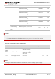
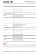
Table 36: Power Supply Ratings of GNSS Part
Parameter Description Conditions Min. Typ. Max. Unit
GNSS_
VCC
Supply voltage
Voltage must stay
within the min/max
values, including
voltage drop, ripple,
and spikes.
2.8 3.3 4.3 V
I
VCCP
1)
Peak supply current VCC=3.3V 150 mA
1)
This figure can be used to determine the maximum current capability of power supply.
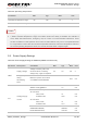
DATA mode, GPRS (3Rx, 2Tx)
GSM850/EGSM900
1)
DCS1800/PCS1900
2)
359/360
232/250
mA
mA
DATA mode, GPRS (2 Rx, 3Tx)
GSM850/EGSM900
1)
DCS1800/PCS1900
2)
431/413
311/339
mA
mA
DATA mode, GPRS (4 Rx, 1Tx)
GSM850/EGSM900
1)
DCS1800/PCS1900
2)
215/153
153/162
mA
mA
DATA mode, GPRS (1Rx, 4Tx)
GSM850/EGSM900
1)
DCS1800/PCS1900
2)
499/469
3)
392/427
mA
mA
Peak supply
current (during
transmission
slot)
Maximum power control level
on GSM850 and EGSM900.
1.6 2 A
NOTES
NOTE