
User's Manual


GSM/GPRS/GNSS Module Series
MC20 Hardware Design
MC20_Hardware_Design Confidential / Released 61 / 95
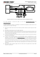
3.9. ADC
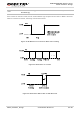
The module provides an ADC channel to measure the value of voltage. Please give priority to the use of
ADC0 channel. Command AT+QADC can read the voltage value applied on ADC0 pin. For details of this
AT command, please refer to document [1]. In order to improve the accuracy of ADC, the layout of ADC
should be surrounded by ground.
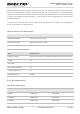
Table 20: Pin Definition of the ADC
Table 21: Characteristics of the ADC
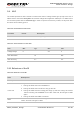
3.10. Behaviors of the RI
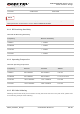
Table 22: Behaviors of the RI
Pin Name Pin No. Description
ADC 6 Analog to digital converter.
Item Min. Typ. Max. Unit
Voltage Range 0 2.8 V
ADC Resolution 10 bits
ADC Accuracy 2.7 mV
State RI Response
Standby HIGH
Voice Call
Change to LOW, and then:
1. Change to HIGH when call is established.
2. Change to HIGH when use ATH to hang up the call
3. Change to HIGH first when calling part hangs up and then change to LOW for
120ms indicating “NO CARRIER” as an URC. After that, RI changes to HIGH
again.
4. Change to HIGH when SMS is received.
SMS
When a new SMS comes, the RI changes to LOW and holds low level for about
120ms, and then changes to HIGH.