
User's Manual

GSM/GPRS/GNSS Module Series
MC20 Hardware Design
MC20_Hardware_Design Confidential / Released 53 / 95
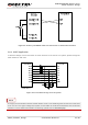
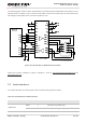
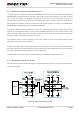
AIN can be used for input of microphone and line. An electret microphone is usually used. AIN are
differential input channels.
AOUT1 is used for output of receiver. The channel is typically used for building a receiver into a handset.
AOUT1 channel is a differential channel.
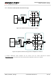
AOUT2 is used for loudspeaker output as it is embedded with an amplifier of class AB whose maximum
drive power is 800mW. AOUT2 is a differential channel.
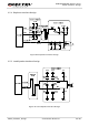
AOUT2 also can be used for output of earphone, and can be used as a single-ended channel.
All these audio channels support voice and ringtone output, and so on, and can be switched by
AT+QAUDCH command. For more details, please refer to document [1].
Use AT command AT+QAUDCH to select audio channel:
0--AIN/AOUT1, the default value is 0.
1--AIN/AOUT2, this channel is always used for earphone.
2--AIN/AOUT2, this channel is always used for loudspeaker.
For each channel, you can use AT+QMIC to adjust the input gain level of microphone. You can also use
AT+CLVL to adjust the output gain level of receiver and speaker. AT+QSIDET is used to set the
side-tone gain level. For more details, please refer to document [1].
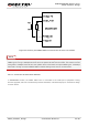
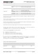
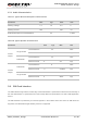
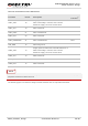
Table 16: AOUT2 Output Characteristics
SPKP 3 Channel 1 Audio positive output
SPKN 4 Channel 1 Audio negative output
AIN/AOUT2
MICP 1 Microphone positive input
MICN 2 Microphone negative input
LOUDSPKP 54 Channel 2 Audio positive output
LOUDSPKN 53 Channel 2 Audio negative output
Item Condition Min. Typ. Max. Unit
RMS Power
8ohm load
VBAT=3.7v
THD+N=1%
800 mW