
User's Manual

GSM/GPRS/GNSS Module Series
MC20 Hardware Design
MC20_Hardware_Design Confidential / Released 52 / 95
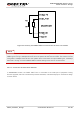
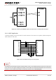
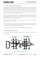
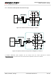
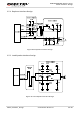
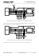
The following figure shows a sketch map between the module and the standard RS-232 interface. As the
electrical level of module is 2.8V, a RS-232 level shifter must be used. Note that you should assure the
I/O voltage of level shifter which connects to module is 2.8V.
Figure 24: Sketch Map for RS-232 Interface Match
Please visit vendors’ websites to select a suitable IC, such as: http://www.maximintegrated.com and
http://www.exar.com/.
3.7. Audio Interfaces
The module provides one analog input channel and two analog output channels.
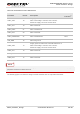
Table 15: Pin Definition of Audio Interface
Interface Pin Name Pin No. Description
AIN/AOUT1
MICP 1 Microphone positive input
MICN 2 Microphone negative input