
User's Manual

GSM/GPRS/GNSS Module Series
MC20 Hardware Design
MC20_Hardware_Design Confidential / Released 51 / 95
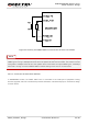
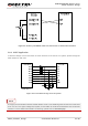
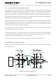
Figure 22: Auxiliary and GNSS UART Port Connection in Stand-alone Solution
3.6.4. UART Application
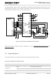
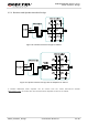
A reference design of 3.3V level match is shown as below. If the host is a 3V system, please change the
5.6K resistors to 10K ones.
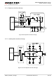
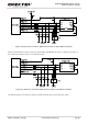
Figure 23: Level Match Design for 3.3V System
It is highly recommended to add the resistor divider circuit on the UART signal lines when the host’s level
is 3V or 3.3V. For a higher voltage level system, a level shifter IC could be used between the host and the
module. For more details about UART circuit design, please refer to document [13].
NOTE