
User's Manual

GSM/GPRS/GNSS Module Series
MC20 Hardware Design
MC20_Hardware_Design Confidential / Released 45 / 95
1)
It is recommended to keep these pins open in stand-alone solution, except during firmware upgrade.
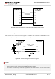
3.6.1. UART Port
3.6.1.1. Features of UART Port
Seven lines on UART interface
Contain data lines TXD and RXD, hardware flow control lines RTS and CTS, as well as other control
lines DTR, DCD and RI.
Used for AT command, GPRS data, etc. Multiplexing function is supported on the UART Port. NMEA
output and PMTK command can be supported in all-in-one solution.
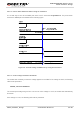
Support the following communication baud rates:
300, 600, 1200, 2400, 4800, 9600, 14400, 19200, 28800, 38400, 57600, 115200bps.
The default setting is autobauding mode. Support the following baud rates for autobauding function:
4800, 9600, 19200, 38400, 57600, 115200bps.
Hardware flow control is disabled by default. When hardware flow control is required, RTS and CTS
should be connected to the host. AT command AT+IFC=2,2 is used to enable hardware flow control.
AT command AT+IFC=0,0 is used to disable the hardware flow control. For more details, please refer
to document [1].
After setting a fixed baud rate or autobauding, please send “AT” string at that rate. The UART port is
ready when it responds “OK”.
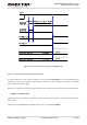
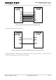
Autobauding allows the module to detect the baud rate by receiving the string “AT” or “at” from the host or
PC automatically, which gives module flexibility without considering which baud rate is used by the host
controller. Autobauding is enabled by default. To take advantage of the autobauding mode, special
attention should be paid according to the following requirements:
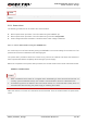
DBG_TXD 29 Transmit data
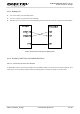
Auxiliary UART Port
1)
RXD_AUX
1)
24 Receive data
TXD_AUX
1)
25 Transmit data
GNSS UART Port
GNSS_RXD 23 Receive data
GNSS_TXD 22 Transmit data
NOTE