
User's Manual

GSM/GPRS/GNSS Module Series
MC20 Hardware Design
MC20_Hardware_Design Confidential / Released 43 / 95
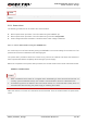
UNDER_VOLTAGE POWER DOWN
After that moment, no further AT commands can be executed. The module logs off from network and
enters into power down mode.
When unsolicited result codes do not appear when autobauding is active and DTE & DCE are not
correctly synchronized after start-up, the module is recommended to be set to a fixed baud rate.
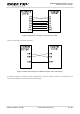
3.6. Serial Interfaces
The module provides four serial ports: UART Port, Debug Port, Auxiliary UART Port and GNSS UART
Port. The module is designed as DCE (Data Communication Equipment), following the traditional
DCE-DTE (Data Terminal Equipment) connection. Autobauding function supports baud rate from
4800bps to 115200bps.
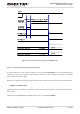
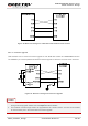
The UART Port:
TXD: Send data to RXD of DTE.
RXD: Receive data from TXD of DTE.
RTS: Request to send.
CTS: Clear to send.
DTR: DTE is ready and inform DCE (this pin can wake the module up).
RI: Ring indicator (when there is a call, SMS or URC output, the module will inform DTE with the RI
pin).
DCD: Data carrier detection (the validity of this pin demonstrates successful set-up of the
communication link).
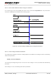
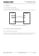
The Debug Port:
DBG_TXD: Send data to the COM port of peripheral.
DBG_RXD: Receive data from the COM port of peripheral.
The Auxiliary UART Port:
In all-in-one solution:
TXD_AUX: Send data to the GNSS part.
RXD_AUX: Receive data from the GNSS part.
In stand-alone solution:
TXD_AUX: Keep open except during firmware upgrade.
NOTE