
User's Manual

GSM/GPRS/GNSS Module Series
MC20 Hardware Design
MC20_Hardware_Design Confidential / Released 38 / 95
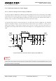
3.5. Power on and down
3.5.1. Power on
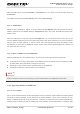
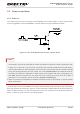
The module can be turned on by driving the pin PWRKEY to a low level voltage. An open collector driver
circuit is suggested to control the PWRKEY. A simple reference circuit is illustrated as below.
Figure 11: Turn on the Module with an Open-collector Driver
1. MC20 module is set to autobauding mode (AT+IPR=0) by default. In autobauding mode, URC RDY is
not reported to the host controller after the module is powered on. When the module is powered on after
a delay of 4 or 5 seconds, it can receive AT commands. Host controller should first send an AT string in
order that the module can detect baud rate of host controller, and it should continue to send the next AT
string until receiving OK string from the module. Then enter AT+IPR=x;&W to set a fixed baud rate for
the module and save the configuration to flash memory of the module. After these configurations, the
URC RDY would be received from the UART Port of the module every time when the module is
powered on. For more details, refer to the section AT+IPR in document [1].
2. When AT command is responded, it indicates the module is turned on successfully; or else the module
fails to be turned on.
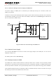
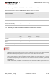
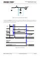
The other way to control the PWRKEY is through a button directly. While pressing the key, electrostatic
strike may generate from the finger, and thus, a TVS component is indispensable to be placed nearby the
button for ESD protection. For the best performance, the TVS component must be placed nearby the
button. A reference circuit is shown in the following figure.
NOTES