
User's Manual

GSM/GPRS/GNSS Module Series
MC20 Hardware Design
MC20_Hardware_Design Confidential / Released 32 / 95
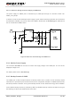
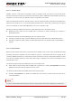
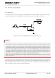
The main power supply (VBAT) is remained
The GSM part is powered on
The GNSS part is turned off by AT+QGNSSC=0 command via UART
In this case, the VRTC pin can be kept floating. A reference schematic diagram is shown below.
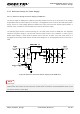
Figure 10: Internal GNSS’s Backup Domain Power Construction
3.4. Operating Modes
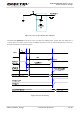
3.4.1. Operating Modes of GSM Part
The table below briefly summarizes the various operating modes of GSM part mentioned in the following
chapters.
Table 9: Operating Modes Overview of GSM Part
Modes Function
GSM Normal
Operation
GSM/GPRS
Sleep
After enabling sleep mode by AT+QSCLK=1, the GSM part will
automatically enter into Sleep Mode if DTR is set to high level
and there is no interrupt (such as GPIO interrupt or data on
UART port). In this case, the current consumption of the GSM
part will reduce to the minimal level.
During Sleep Mode, the GSM part can still receive paging
message and SMS from the system normally.
GSM IDLE
Software is active. The GSM part has registered on GSM
network, and it is ready to send and receive GSM data.
GSM TALK
GSM connection is ongoing. In this mode, the power
consumption is decided by the configuration of Power Control
Level (PCL), dynamic DTX control and the working RF band.