
User's Manual

GSM/GPRS/GNSS Module Series
MC20 Hardware Design
MC20_Hardware_Design Confidential / Released 25 / 95
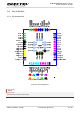
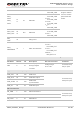
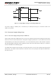
Table 7: Multiplexed Functions
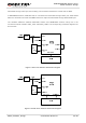
3.2. Application Modes Introduction
MC20 module integrates both GSM and GNSS engines which can work as a whole (all-in-one solution)
unit or work relatively independent (stand-alone solution) according to customer demands.
All-in-one solution allows for convenient communication between GSM and GNSS parts. The commands
and data (e.g. AT and PMTK commands, NMEA sentences output, etc.) in both GSM and GNSS parts are
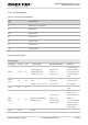
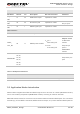
Antenna Interface
PIN Name PIN No. I/O Description DC Characteristics Comment
RF_
ANT
41 IO GSM antenna pad Impedance of 50Ω
BT_
ANT
32 IO BT antenna pad Impedance of 50Ω
If unused, keep
this pin open.
GNSS_
ANT
15 I GNSS signal input Impedance of 50Ω
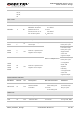
Other Interface
PIN Name PIN No. I/O Description DC Characteristics Comment
GNSS_
VCC_EN
28 O GNSS power enabled
V
OH
min=
0.85×VDD_EXT
V
OL
max=
0.15×VDD_EXT
Refer to
Chapter 3.3.3.2
in all-in-one
solution.
Keep this pin
open in
stand-alone
solution.
RESERVED
17, 46
55, 56,
57, 58,
63, 64,
65, 66,
67, 68,
Keep these pins
open
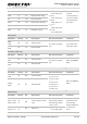
PIN Name PIN No. Function After Reset Alternate Function
DTR/SIM1_PRESENCE 37 DTR SIM1_PRESENCE