
User's Manual

GSM/GPRS/GNSS Module Series
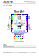
MC20 Hardware Design
MC20_Hardware_Design Confidential / Released 24 / 95
V
OH
min=
0.85×SIM_VDD
Maximum trace
length is 200mm
from the module
pad to SIM card
holder.
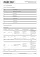
SIM1_
DATA
SIM2_
DATA
21
11
IO SIM data
V
IL
max=
0.25×SIM_VDD
V
IH
min=
0.75×SIM_VDD
V
OL
max=
0.15×SIM_VDD
V
OH
min=
0.85×SIM_VDD
SIM1_ RST
SIM2_ RST
20
12
DO SIM reset
V
OL
max=
0.15×SIM_VDD
V
OH
min=
0.85×SIM_VDD
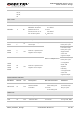
SIM_
GND
16 SIM ground
SIM1_
PRESENCE
37 I SIM1 card detection
V
IL
min =0V
V
IL
max =
0.25×VDD_EXT
V
IH
min =
0.75×VDD_EXT
VIHmax =
VDD_EXT+0.2
ADC
PIN Name PIN No. I/O Description DC Characteristics Comment
ADC 6 AI
General purpose
analog to digital
converter.
Voltage range:
0V to 2.8V
If unused, keep
this pin open.
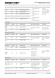
Digital Audio Interface (PCM)
PCM_CLK 59 DO PCM clock
If unused, keep
these pins open
PCM_OUT 60 DO PCM data output
PCM_SYNC 61 DO
PCM frame
synchronization
PCM_IN 62 DI PCM data input
SD Card Interface
SD_CMD 7 DO SD Command line
If unused, keep
these pins open
SD_CLK 8 DO SD clock
SD_DATA 9 IO SD data line