
User's Manual


0
LTE Module
EC25-A User Manual
EC25-A_User_Manual Confidential / Released 48 / 7
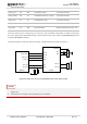
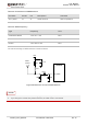
5.1.3. Reference Design
The reference design of ANT_MAIN and ANT_DIV antenna is shown as below. It should reserve a π-type
matching circuit for better RF performance. The capacitors are not mounted by default.
ANT_MAIN
R1 0R
C1
Module
Main
antenna
NM
C2
NM
R2 0R
C3
Diversity
antenna
NM
C4
NM
ANT_DIV
Figure 27: Reference Circuit of Antenna Interface
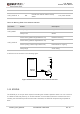
1. Keep a proper distance between the main antenna and the Rx-diversity antenna to improve the
receiving sensitivity.
2. ANT_DIV function is enabled by default. Use the AT command AT+QCFG="diversity",0 can disable
receive diversity.
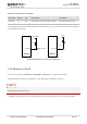
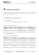
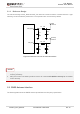
5.2. GNSS Antenna Interface
The following tables show the GNSS antenna pin definition and frequency specification.
NOTES