
User's Manual


GSM/GPRS Module Series
M26 Hardware Design
M26_Hardware_Design Confidential / Released 40 / 80
3.8. Audio Interfaces
The module provides one analog input channels and two analog output channels.
Table 9: Pin Definition of Audio Interface
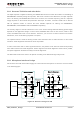
AIN can be used for input of microphone and line. An electret microphone is usually used. AIN are
differential input channels.
AOUT1 is used for output of the receiver. This channel is typically used for a receiver built into a handset.
AOUT1 channel is a differential channel.
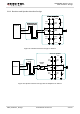
AOUT2 is typically used with earphone. It is a single-ended and mono channel. SPK2P and AGND can
establish a pseudo differential mode.
All of these two audio channels support voice and ringtone output, and so on, and can be switched by
AT+QAUDCH command. For more details, please refer to the document [1].
Use AT command AT+QAUDCH to select audio channel:
0--AIN/AOUT1, the default value is 0.
1--AIN/AOUT2, this channel is always used for earphone.
For each channel, you can use AT+QMIC to adjust the input gain level of microphone. You can also use
AT+CLVL to adjust the output gain level of receiver and speaker. AT+QSIDET is used to set the
side-tone gain level. For more details, please refer to the document [1].
Interface
Pin Name
Pin No.
Description
AIN/AOUT1
MICP
3
Microphone positive input
MICN
4
Microphone negative input
SPK1P
5
Channel 1 Audio positive output
SPK1N
6
Channel 1 Audio negative output
AIN/AOUT2
MICP
3
Microphone positive input
MICN
4
Microphone negative input
SPK2P
2
Channel 2 Audio positive output
AGND
1
Form a pseudo-differential pair with SPK2P