
User's Manual

LTE Module
EC20 Hardware Design
EC20_Hardware_Design Confidential / Released 50 / 83
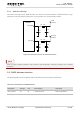
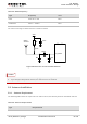
5.1.3. Reference Design
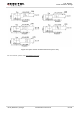
The reference design of ANT_MAIN and ANT_DIV antenna is shown as below. It should reserve a π-type
matching circuit for better RF performance. The capacitors are not mounted by default.
ANT_MAIN
R1 0R
C1
Module
Main
antenna
NM
C2
NM
R2 0R
C3
Diversity
antenna
NM
C4
NM
ANT_DIV
Figure 27: Reference Circuit of Antenna Interface
Keep a proper distance between main antenna and Rx-diversity antenna to improve the receiving
sensitivity.
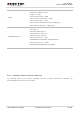
5.2. GNSS Antenna Interface
The following tables show the GNSS antenna pin definition and frequency specification.
Table 24: Pin Definition of GNSS Antenna
Pin Name
Pin No.
I/O
Description
Comment
ANT_GNSS
47
AI
GNSS antenna
50ohm impedance
NOTE