
User's Manual

LTE Module
EC20 Hardware Design
EC20_Hardware_Design Confidential / Released 34 / 83
3.9. USIM Card Interface
The USIM card interface circuitry meets ETSI and IMT-2000 SIM interface requirements. Both 1.8V and
3.0V USIM cards are supported.
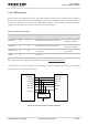
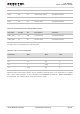
Table 9: Pin Definition of the USIM Interface
Pin Name
Pin No.
I/O
Description
Comment
USIM_VDD
14
PO
Power supply for USIM card.
Either 1.8V or 3.0V is supported
by the module automatically.
USIM_DATA
15
IO
Data signal of USIM card.
USIM_CLK
16
DO
Clock signal of USIM card.
USIM_RST
17
DO
Reset signal of USIM card.
USIM_PRE
SENCE
13
DI
USIM card insertion detection.
USIM_GND
10
Specified ground for USIM card.
EC20 supports USIM card hot-plug via the USIM_PRESENCE pin. It supports low level and high level
detection, which is disabled by default. For details, refer to document [2] about the command
AT+QSIMDET.
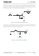
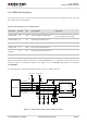
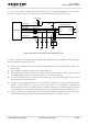
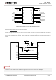
The following figure shows the reference design of the 8-pin USIM connector.
Module
USIM_VDD
USIM_GND
USIM_RST
USIM_CLK
USIM_DATA
USIM_PRESENCE
22R
22R
22R
VDD_EXT
51K
100nF USIM Connector
GND
GND
33pF
33pF 33pF
VCC
RST
CLK
IO
VPP
GND
GND
USIM_VDD
15K
Figure 17: Reference Circuit of 8-Pin USIM Connector