
User's Manual

LTE Module
EC20 Hardware Design
EC20_Hardware_Design Confidential / Released 29 / 83
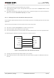
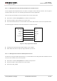
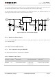
use a LDO to supply power for module. If there is a big voltage difference between the input source and
the desired output (VBAT), a buck converter is preferred to be used as a power supply.
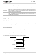
The following figure shows a reference design for +5V input power source. The designed output for the
power supply is about 3.8V and the maximum load current is 3A.
DC_IN
MIC29302WU
IN OUT
EN
GND
ADJ
2 4
1
3
5
VBAT
100nF
470uF
100nF
100K
47K
470uF
470R
51K
1%
1%
4.7K
47K
VBAT_EN
Figure 9: Reference Circuit of Power Supply
3.6.4. Monitor the Power Supply
You can use the AT+CBC command to monitor the VBAT_BB voltage value. For more details, please
refer to document [2].
3.7. Turn on and off Scenarios
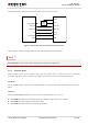
3.7.1. Turn on Module Using the PWRKEY
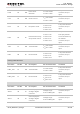
The following table shows the pin definition of PWRKEY.
Table 7: PWRKEY Pin Description
Pin Name
Pin No.
Description
DC Characteristics
Comment
PWRKEY
21
Turn on/off the module.
V
IH
max=2.1V
V
IH
min=1.3V
V
IL
max=0.5V
Pull-up to 1.8V internally.