
User's Manual

LTE Module
EC20 Hardware Design
EC20_Hardware_Design Confidential / Released 27 / 83
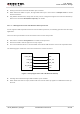
1. The W_DISABLE# control function is disabled in firmware by default. It can be enabled by AT
command AT+QCFG=“airplanecontrol”. Refer to document [2].
2. The execution of AT+CFUN command will not affect GNSS function.
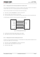
3.6. Power Supply
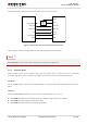
3.6.1. Power Supply Pins
EC20 provides four VBAT pins dedicated to connect with the external power supply. There are two
separate voltage domains for VBAT.
VBAT_RF with two pins for module RF part.
VBAT_BB with two pins for module baseband part.
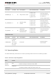
The following table shows the VBAT pins and ground pins.
Table 6: VBAT and GND Pins
Pin Name
Pin No.
Description
Min.
Typ.
Max.
Unit
VBAT_RF
57, 58
Power supply for module RF
part.
3.3
3.8
4.3
V
VBAT_BB
59, 60
Power supply for module
baseband part.
3.3
3.8
4.3
V
GND
8, 9, 19, 22, 36,
46, 48, 50~54,
56, 72, 85~112
Ground.
-
0
-
V
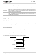
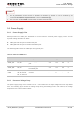
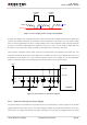
3.6.2. Decrease Voltage Drop
The power supply range of the module is 3.3V ~ 4.3V. Make sure the input voltage will never drop below
3.3V. The following figure shows the voltage drop during transmitting burst in 2G network, the voltage
drop will be less in 3G and 4G network.
NOTES