
User's Manual

LTE Module
EC20 Hardware Design
EC20_Hardware_Design Confidential / Released 26 / 83
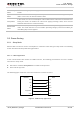
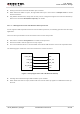
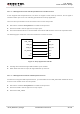
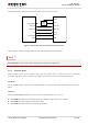
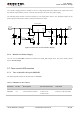
The following figure shows the connection between the module and host.
USB_VBUS
USB_DP
USB_DM
AP_READY
VDD
USB_DP
USB_DM
GPIO
Module Host
RI
EINT
Power
Switch
GPIO
GND
GND
Figure 6: Sleep Application without Suspend Function
Opening power switch to supply power to USB_VBUS will wake up the module.
You should pay attention to the level match shown in dotted line between module and host. Refer to
document [1] for more details about EC20 power management application.
3.5.2. Airplane Mode
When module enters into the airplane mode, the RF function does not work, and all AT commands
correlative with RF function will not be accessible. This mode can be set with the following ways.
Hardware:
The W_DISABLE# pin is pulled up by default, driving it to low level will let the module enter into airplane
mode.
Software:
Command AT+CFUN provides the choice of the functionality level <fun>=0, 1, 4.
AT+CFUN=0: Minimum functionality mode, both USIM and RF function are disabled.
AT+CFUN=1: Full functionality mode (by default).
AT+CFUN=4: Airplane mode. RF function is disabled.
NOTE