
User's Manual

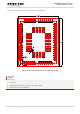

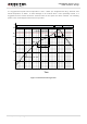

Table Of Contents
- About the Document
- Contents
- Table Index
- Figure Index
- 1 Introduction
- 2 Product Concept
- 3 Application Interface
- 3.1. General Description
- 3.2. Pin Assignment
- 3.3. Pin Description
- 3.4. Operating Modes
- 3.5. Power Saving
- 3.6. Power Supply
- 3.7. Turn on and off Scenarios
- 3.8. Reset the Module
- 3.9. RTC Interface
- 3.10. UART Interface
- 3.11. USIM Card Interface
- 3.12. USB Interface
- 3.13. PCM and I2C Interface
- 3.14. Network Status Indication
- 3.15. Operating Status Indication
- 4 Antenna Interface
- 5 Electrical, Reliability and Radio Characteristics
- 6 Mechanical Dimensions
- 7 Storage and Manufacturing
- 8 Appendix A Reference
- 9 Appendix B GPRS Coding Scheme
- 10 Appendix C GPRS Multi-slot Class
- 11 Appendix D EDGE Modulation and Coding Scheme

UMTS/HSPA Module Series
UG96 Hardware Design
UG96_Hardware_Design Confidential / Released 67 / 75
It is suggested that peak reflow temperature is 235 ~ 245ºC (for SnAg3.0Cu0.5 alloy). Absolute max
reflow temperature is 260ºC. To avoid damage to the module when it was repeatedly heated, it is
suggested that the module should be mounted after the first panel has been reflowed. The following
picture is the actual diagram which we have operated.
Time
50
100
150 200
250 300
50
100
150
200
250
160 ºC
200 ºC
217
0
70s~120s
40s~60s
Between 1~3 ºC/s
Preheat Heating Cooling
ºC
s
Liquids Temperature
Figure 41: Reflow Soldering Profile