
User's Manual
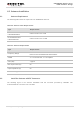


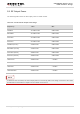
Table Of Contents
- About the Document
- Contents
- Table Index
- Figure Index
- 1 Introduction
- 2 Product Concept
- 3 Application Interface
- 3.1. General Description
- 3.2. Pin Assignment
- 3.3. Pin Description
- 3.4. Operating Modes
- 3.5. Power Saving
- 3.6. Power Supply
- 3.7. Turn on and off Scenarios
- 3.8. Reset the Module
- 3.9. RTC Interface
- 3.10. UART Interface
- 3.11. USIM Card Interface
- 3.12. USB Interface
- 3.13. PCM and I2C Interface
- 3.14. Network Status Indication
- 3.15. Operating Status Indication
- 4 Antenna Interface
- 5 Electrical, Reliability and Radio Characteristics
- 6 Mechanical Dimensions
- 7 Storage and Manufacturing
- 8 Appendix A Reference
- 9 Appendix B GPRS Coding Scheme
- 10 Appendix C GPRS Multi-slot Class
- 11 Appendix D EDGE Modulation and Coding Scheme

UMTS/HSPA Module Series
UG96 Hardware Design
UG96_Hardware_Design Confidential / Released 59 / 75
5.5. RF Output Power
The following table shows the RF output power of UG96 module.
Table 26: Conducted RF Output Power Edge
Frequency
Max.
Min.
GSM850
32.5dBm±1dB
5dBm±5dB
EGSM900
32.5dBm±1dB
5dBm±5dB
DCS1800
29.5dBm±1dB
0dBm±5dB
PCS1900
29.5dBm±1dB
0dBm±5dB
GSM850 (8-PSK)
27dBm±1dB
5dBm±5dB
EGSM900 (8-PSK)
27dBm±1dB
5dBm±5dB
DCS1800 (8-PSK)
26dBm±1dB
0dBm±5dB
PCS1900 (8-PSK)
26dBm±1dB
0dBm±5dB
UMTS2100
22dBm±1dB
<-50dBm
UMTS1900
22dBm±1dB
<-50dBm
UMTS900
22dBm±1dB
<-50dBm
UMTS850/800
22dBm±1dB
<-50dBm
In GPRS 4 slots TX mode, the max output power is reduced by 3dB. This design conforms to the GSM
specification as described in chapter 13.16 of 3GPP TS 51.010-1.
NOTE