
User's Manual

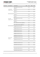


Table Of Contents
- About the Document
- Contents
- Table Index
- Figure Index
- 1 Introduction
- 2 Product Concept
- 3 Application Interface
- 3.1. General Description
- 3.2. Pin Assignment
- 3.3. Pin Description
- 3.4. Operating Modes
- 3.5. Power Saving
- 3.6. Power Supply
- 3.7. Turn on and off Scenarios
- 3.8. Reset the Module
- 3.9. RTC Interface
- 3.10. UART Interface
- 3.11. USIM Card Interface
- 3.12. USB Interface
- 3.13. PCM and I2C Interface
- 3.14. Network Status Indication
- 3.15. Operating Status Indication
- 4 Antenna Interface
- 5 Electrical, Reliability and Radio Characteristics
- 6 Mechanical Dimensions
- 7 Storage and Manufacturing
- 8 Appendix A Reference
- 9 Appendix B GPRS Coding Scheme
- 10 Appendix C GPRS Multi-slot Class
- 11 Appendix D EDGE Modulation and Coding Scheme

UMTS/HSPA Module Series
UG96 Hardware Design
UG96_Hardware_Design Confidential / Released 57 / 75
Parameter
Description
Conditions
Min.
Typ.
Max.
Unit
DCS1800 1DL/4UL PCL=0
397
mA
PCS1900 1DL/1UL PCL=0
189
mA
PCS1900 4DL/1UL PCL=0
204
mA
PCS1900 3DL/2UL PCL=0
330
mA
PCS1900 2DL/3UL PCL=0
407
mA
PCS1900 1DL/4UL PCL=0
434
mA
EDGE data
transfer
GSM850 1DL/1UL PCL=8
187
mA
GSM850 4DL/1UL PCL=8
199
mA
GSM850 3DL/2UL PCL=8
312
mA
GSM850 2DL/3UL PCL=8
412
mA
GSM850 1DL/4UL PCL=8
504
mA
EGSM900 1DL/1UL PCL=8
184
mA
EGSM900 4DL/1UL PCL=8
197
mA
EGSM900 3DL/2UL PCL=8
305
mA
EGSM900 2DL/3UL PCL=8
406
mA
EGSM900 1DL/4UL PCL=8
500
mA
DCS1800 1DL/1UL PCL=2
197
mA
DCS1800 4DL/1UL PCL=2
205
mA
DCS1800 3DL/2UL PCL=2
309
mA
DCS1800 2DL/3UL PCL=2
400
mA
DCS1800 1DL/4UL PCL=2
482
mA
PCS1900 1DL/1UL PCL=2
200
mA
PCS1900 4DL/1UL PCL=2
201
mA
PCS1900 3DL/2UL PCL=2
310
mA