
User's Manual
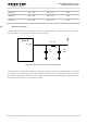
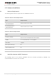
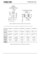

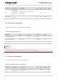
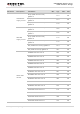


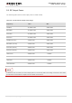
Table Of Contents
- About the Document
- Contents
- Table Index
- Figure Index
- 1 Introduction
- 2 Product Concept
- 3 Application Interface
- 3.1. General Description
- 3.2. Pin Assignment
- 3.3. Pin Description
- 3.4. Operating Modes
- 3.5. Power Saving
- 3.6. Power Supply
- 3.7. Turn on and off Scenarios
- 3.8. Reset the Module
- 3.9. RTC Interface
- 3.10. UART Interface
- 3.11. USIM Card Interface
- 3.12. USB Interface
- 3.13. PCM and I2C Interface
- 3.14. Network Status Indication
- 3.15. Operating Status Indication
- 4 Antenna Interface
- 5 Electrical, Reliability and Radio Characteristics
- 6 Mechanical Dimensions
- 7 Storage and Manufacturing
- 8 Appendix A Reference
- 9 Appendix B GPRS Coding Scheme
- 10 Appendix C GPRS Multi-slot Class
- 11 Appendix D EDGE Modulation and Coding Scheme

UMTS/HSPA Module Series
UG96 Hardware Design
UG96_Hardware_Design Confidential / Released 55 / 75
Parameter
Description
Conditions
Min.
Typ.
Max.
Unit
I
VBAT
Peak supply
current (during
transmission
slot)
Maximum power control level on
EGSM900.
1.8
2.0
A
USB_VBUS
USB insert
detection
2.5
5.0
5.25
V
5.3. Operating Temperature
The operating temperature is listed in the following table.
Table 24: Operating Temperature
Parameter
Min.
Typ.
Max.
Unit
Normal Temperature
-35
25
80
ºC
Restricted Operation
1)
-40~ -35
80 ~ 85
ºC
Storage Temperature
-45
90
ºC
1)
When the module works within the temperature range, the deviations from the RF specification may
occur. For example, the frequency error or the phase error would increase.
5.4. Current Consumption
The values of current consumption are shown below.
Table 25: The Module Current Consumption
Parameter
Description
Conditions
Min.
Typ.
Max.
Unit
I
VBAT
OFF state
supply current
Power down
126
uA
NOTE