
User's Manual
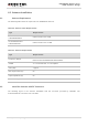

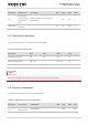
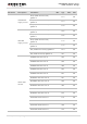


Table Of Contents
- About the Document
- Contents
- Table Index
- Figure Index
- 1 Introduction
- 2 Product Concept
- 3 Application Interface
- 3.1. General Description
- 3.2. Pin Assignment
- 3.3. Pin Description
- 3.4. Operating Modes
- 3.5. Power Saving
- 3.6. Power Supply
- 3.7. Turn on and off Scenarios
- 3.8. Reset the Module
- 3.9. RTC Interface
- 3.10. UART Interface
- 3.11. USIM Card Interface
- 3.12. USB Interface
- 3.13. PCM and I2C Interface
- 3.14. Network Status Indication
- 3.15. Operating Status Indication
- 4 Antenna Interface
- 5 Electrical, Reliability and Radio Characteristics
- 6 Mechanical Dimensions
- 7 Storage and Manufacturing
- 8 Appendix A Reference
- 9 Appendix B GPRS Coding Scheme
- 10 Appendix C GPRS Multi-slot Class
- 11 Appendix D EDGE Modulation and Coding Scheme

UMTS/HSPA Module Series
UG96 Hardware Design
UG96_Hardware_Design Confidential / Released 54 / 75
5 Electrical, Reliability and Radio
Characteristics
5.1. Absolute Maximum Ratings
Absolute maximum ratings for power supply and voltage on digital and analog pins of module are listed in
the following table.
Table 22: Absolute Maximum Ratings
Parameter
Min.
Max.
Unit
VBAT_RF/VBAT_BB
-0.3
4.7
V
USB_VBUS
-0.3
5.5
V
Peak Current of VBAT_BB
0
0.8
A
Peak Current of VBAT_RF
0
2
A
Voltage at Digital Pins
-0.3
2.3
V
5.2. Power Supply Ratings
Table 23: The Module Power Supply Ratings
Parameter
Description
Conditions
Min.
Typ.
Max.
Unit
VBAT
VBAT_BB and
VBAT_RF
Voltage must stay within the
min/max values, including voltage
drop, ripple, and spikes.
3.3
3.8
4.3
V
Voltage drop
during
transmitting
burst
Maximum power control level on
EGSM900.
400
mV