
User's Manual
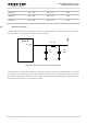
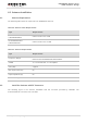
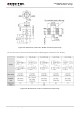
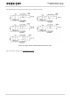


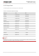
Table Of Contents
- About the Document
- Contents
- Table Index
- Figure Index
- 1 Introduction
- 2 Product Concept
- 3 Application Interface
- 3.1. General Description
- 3.2. Pin Assignment
- 3.3. Pin Description
- 3.4. Operating Modes
- 3.5. Power Saving
- 3.6. Power Supply
- 3.7. Turn on and off Scenarios
- 3.8. Reset the Module
- 3.9. RTC Interface
- 3.10. UART Interface
- 3.11. USIM Card Interface
- 3.12. USB Interface
- 3.13. PCM and I2C Interface
- 3.14. Network Status Indication
- 3.15. Operating Status Indication
- 4 Antenna Interface
- 5 Electrical, Reliability and Radio Characteristics
- 6 Mechanical Dimensions
- 7 Storage and Manufacturing
- 8 Appendix A Reference
- 9 Appendix B GPRS Coding Scheme
- 10 Appendix C GPRS Multi-slot Class
- 11 Appendix D EDGE Modulation and Coding Scheme

UMTS/HSPA Module Series
UG96 Hardware Design
UG96_Hardware_Design Confidential / Released 51 / 75
4.2. Antenna Installation
4.2.1. Antenna Requirement
The following table shows the requirement on GSM/UMTS antenna.
Table 20: Antenna Cable Requirements
Type
Requirements
GSM850/EGSM900
UMTS800/850/900
Cable insertion loss <1dB
DCS1800/PCS1900
UMTS1900/2100
Cable insertion loss <1.5dB
Table 21: Antenna Requirements
Type
Requirements
Frequency Range
GSM 4-band: 850/900/1800/1900MHz
UMTS 5-band: 800/850/900/1900/2100MHz
VSWR
<2:1 recommended, <3:1 acceptable
Gain (dBi)
1 typical
Max Input Power (W)
50
Input Impedance (Ω)
50
Polarization Type
Vertical
4.2.2. Install the Antenna with RF Connector
The following figure is the antenna installation with RF connector provided by HIROSE. The
recommended RF connector is UF.L-R-SMT.