
User's Manual
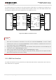
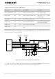
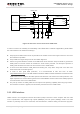
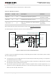
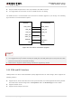
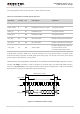
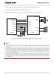
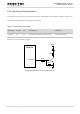
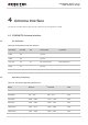
Table Of Contents
- About the Document
- Contents
- Table Index
- Figure Index
- 1 Introduction
- 2 Product Concept
- 3 Application Interface
- 3.1. General Description
- 3.2. Pin Assignment
- 3.3. Pin Description
- 3.4. Operating Modes
- 3.5. Power Saving
- 3.6. Power Supply
- 3.7. Turn on and off Scenarios
- 3.8. Reset the Module
- 3.9. RTC Interface
- 3.10. UART Interface
- 3.11. USIM Card Interface
- 3.12. USB Interface
- 3.13. PCM and I2C Interface
- 3.14. Network Status Indication
- 3.15. Operating Status Indication
- 4 Antenna Interface
- 5 Electrical, Reliability and Radio Characteristics
- 6 Mechanical Dimensions
- 7 Storage and Manufacturing
- 8 Appendix A Reference
- 9 Appendix B GPRS Coding Scheme
- 10 Appendix C GPRS Multi-slot Class
- 11 Appendix D EDGE Modulation and Coding Scheme

UMTS/HSPA Module Series
UG96 Hardware Design
UG96_Hardware_Design Confidential / Released 49 / 75
4 Antenna Interface
The Pin 60 is the RF antenna pad. The RF interface has an impedance of 50Ω.
4.1. GSM/UMTS Antenna Interface
4.1.1. Pin Definition
Table 18: Pin Definition of the RF Antenna
Pin Name
Pin No.
I/O
Description
Comment
GND
58
ground
GND
59
ground
RF_ANT
60
IO
RF antenna pad
50Ω impedance
GND
61
ground
GND
62
ground
4.1.2. Operating Frequency
Table 19: The Module Operating Frequencies
Band
Receive
Transmit
Unit
GSM850
869 ~ 894
824 ~ 849
MHz
EGSM900
925 ~ 960
880 ~ 915
MHz
DCS1800
1805 ~ 1880
1710 ~ 1785
MHz
PCS1900
1930 ~ 1990
1850 ~ 1910
MHz
UMTS2100
2110 ~ 2170
1920 ~ 1980
MHz
UMTS1900
1930 ~ 1990
1850 ~ 1910
MHz