
User's Manual
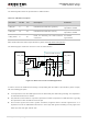
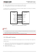
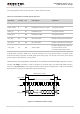
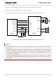
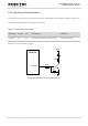
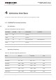
Table Of Contents
- About the Document
- Contents
- Table Index
- Figure Index
- 1 Introduction
- 2 Product Concept
- 3 Application Interface
- 3.1. General Description
- 3.2. Pin Assignment
- 3.3. Pin Description
- 3.4. Operating Modes
- 3.5. Power Saving
- 3.6. Power Supply
- 3.7. Turn on and off Scenarios
- 3.8. Reset the Module
- 3.9. RTC Interface
- 3.10. UART Interface
- 3.11. USIM Card Interface
- 3.12. USB Interface
- 3.13. PCM and I2C Interface
- 3.14. Network Status Indication
- 3.15. Operating Status Indication
- 4 Antenna Interface
- 5 Electrical, Reliability and Radio Characteristics
- 6 Mechanical Dimensions
- 7 Storage and Manufacturing
- 8 Appendix A Reference
- 9 Appendix B GPRS Coding Scheme
- 10 Appendix C GPRS Multi-slot Class
- 11 Appendix D EDGE Modulation and Coding Scheme

UMTS/HSPA Module Series
UG96 Hardware Design
UG96_Hardware_Design Confidential / Released 48 / 75
3.15. Operating Status Indication
The STATUS pin is set as the module status indicator. It will output high level when module is powered on.
The following table describes pin definition of STATUS.
Table 17: Pin Definition of STATUS
Pin Name
Pin No. I/O
Description
Comment
STATUS
20
DO
Indicate the module operation status.
1.8V power domain
A reference circuit is shown as below.
4.7K
47K
VBAT
2.2K
Module
STATUS
Figure 30: Reference Circuit of the STATUS