
User's Manual
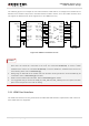
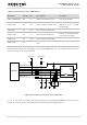
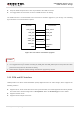
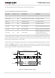
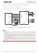
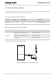
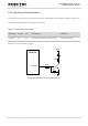
Table Of Contents
- About the Document
- Contents
- Table Index
- Figure Index
- 1 Introduction
- 2 Product Concept
- 3 Application Interface
- 3.1. General Description
- 3.2. Pin Assignment
- 3.3. Pin Description
- 3.4. Operating Modes
- 3.5. Power Saving
- 3.6. Power Supply
- 3.7. Turn on and off Scenarios
- 3.8. Reset the Module
- 3.9. RTC Interface
- 3.10. UART Interface
- 3.11. USIM Card Interface
- 3.12. USB Interface
- 3.13. PCM and I2C Interface
- 3.14. Network Status Indication
- 3.15. Operating Status Indication
- 4 Antenna Interface
- 5 Electrical, Reliability and Radio Characteristics
- 6 Mechanical Dimensions
- 7 Storage and Manufacturing
- 8 Appendix A Reference
- 9 Appendix B GPRS Coding Scheme
- 10 Appendix C GPRS Multi-slot Class
- 11 Appendix D EDGE Modulation and Coding Scheme

UMTS/HSPA Module Series
UG96 Hardware Design
UG96_Hardware_Design Confidential / Released 47 / 75
3.14. Network Status Indication
The NETLIGHT signal can be used to drive a network status indication LED. The following tables describe
pin definition and logic level changes in different network status.
Table 15: Pin Definition of Network Indicator
Pin Name
Pin No. I/O
Description
Comment
NETLIGHT
21
DO
Indicate the module network activity
status.
1.8V power domain.
Table 16: Working State of the Network Indicator
Pin Name
Status
Description
NETLIGHT
PWM (200ms High/1800ms Low)
Network searching
PWM (1800ms High/200ms Low)
Idle&Data transfer
Always High
Voice&CSD calling
A reference circuit is shown in the following figure.
4.7K
47K
VBAT
2.2K
Module
NETLIGHT
Figure 29: Reference Circuit of the NETLIGHT