
User's Manual
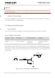
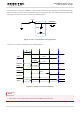


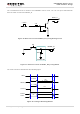
Table Of Contents
- About the Document
- Contents
- Table Index
- Figure Index
- 1 Introduction
- 2 Product Concept
- 3 Application Interface
- 3.1. General Description
- 3.2. Pin Assignment
- 3.3. Pin Description
- 3.4. Operating Modes
- 3.5. Power Saving
- 3.6. Power Supply
- 3.7. Turn on and off Scenarios
- 3.8. Reset the Module
- 3.9. RTC Interface
- 3.10. UART Interface
- 3.11. USIM Card Interface
- 3.12. USB Interface
- 3.13. PCM and I2C Interface
- 3.14. Network Status Indication
- 3.15. Operating Status Indication
- 4 Antenna Interface
- 5 Electrical, Reliability and Radio Characteristics
- 6 Mechanical Dimensions
- 7 Storage and Manufacturing
- 8 Appendix A Reference
- 9 Appendix B GPRS Coding Scheme
- 10 Appendix C GPRS Multi-slot Class
- 11 Appendix D EDGE Modulation and Coding Scheme

UMTS/HSPA Module Series
UG96 Hardware Design
UG96_Hardware_Design Confidential / Released 37 / 75
3.9. RTC Interface
The RTC (Real Time Clock) can be powered by an external capacitor through the pin VRTC when the
module is powered down and there is no power supply for the VBAT. If the voltage supply at VBAT is
disconnected, the RTC can be powered by the capacitor. The capacitance determines the duration of
buffering when no voltage is applied to UG96.
The capacitor is charged from the internal LDO of UG96 when there is power supply for the VBAT. A
serial 1KΩ resistor has been placed on the application inside the module. It limits the input current of the
capacitor.
The following figure shows the reference circuit for VRTC backup.
Large
Capacitance
Capacitor
Module
RTC
Core
1K
VRTC
C
Figure 19: RTC Supply from Capacitor
In order to evaluate the capacitance of capacitor according to the backup time, you have to consider the
following parameters:
VRTC - The starting voltage of the capacitor. (Volt)
VRTC
MIN
- The minimum voltage acceptable for the RTC circuit.(Volt)
I - The current consumption of the RTC circuitry when VBAT = 0.(Ampere)
B
Time
- Backup Time.(Second)
C - The backup capacitance. (Farad)
When the power is off and only VRTC is running, the way of calculating the backup capacitor as follows:
C= B
Time
*I/ (VRTC-VRTC
MIN
)
For example, when the capacitor is 1000uF:
VRTC=1.8V
VRTC
MIN
=1.0V
I=2uA
C=1000uF
The backup time is about 400s.