
User's Manual
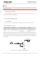
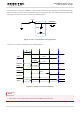


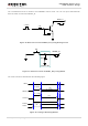
Table Of Contents
- About the Document
- Contents
- Table Index
- Figure Index
- 1 Introduction
- 2 Product Concept
- 3 Application Interface
- 3.1. General Description
- 3.2. Pin Assignment
- 3.3. Pin Description
- 3.4. Operating Modes
- 3.5. Power Saving
- 3.6. Power Supply
- 3.7. Turn on and off Scenarios
- 3.8. Reset the Module
- 3.9. RTC Interface
- 3.10. UART Interface
- 3.11. USIM Card Interface
- 3.12. USB Interface
- 3.13. PCM and I2C Interface
- 3.14. Network Status Indication
- 3.15. Operating Status Indication
- 4 Antenna Interface
- 5 Electrical, Reliability and Radio Characteristics
- 6 Mechanical Dimensions
- 7 Storage and Manufacturing
- 8 Appendix A Reference
- 9 Appendix B GPRS Coding Scheme
- 10 Appendix C GPRS Multi-slot Class
- 11 Appendix D EDGE Modulation and Coding Scheme

UMTS/HSPA Module Series
UG96 Hardware Design
UG96_Hardware_Design Confidential / Released 34 / 75
PWRDWN_N
S2
Close to S2
TVS
Figure 14: Turn off the Module Using Keystroke
The emergency shutdown scenario is illustrated as the following figure.
VBAT
PWRDWN_N
≥100ms
RUNNING
Power-down procedure
OFF
STATUS
Module
Status
Figure 15: Timing of Emergency Shutdown
Use the PWRDWN_N only when turning off the module by the command AT+QPOWD or the RESET_N
pin failed.
NOTE